Wednesday, December 10, 2008

THE MATERIALITY OF THE SPACE

THESIS PROJECT
Architectural Components (from Phaenotype to Genotype)

The idea was to continue working with parametric software in order to design a space with the capacity of combining a self structured parametric skin with elements capable to control the radiosity and sound effects. The cell has a size capable to fit at least 10 people at one time, but the main issue is that it has the possibility to modify its overall shape or components by changing the parameters which are taken from the surrounding environment; some of which are the amount of light, terrain inclinations, inner space needed, etc. In order to explore its materiality and to allow a natural growth based on the main configuration of the geometry and the material itself, each individual component creates a grid capable to stretch and generate new variations.


The honeycombs are capable of tiling a plane with minimal surface area, even though its main strength is based on the superposition of elements. Considering this characteristic and avoiding to have only an ornamental lattice; a relation of geometric constraints integrate a self structured cell in which every element is independent in terms of depth and size but at the same time works as a group collection when it comes to integrate a closed shape. In order to develop a parametric model, an associative protocol had to be followed to integrate every single element into the final cell.

Here you can see a video showing how the model works when the set of parameters and geometric relations are being modified to create new versions of the same prototype.


The structural system has the possibility to support itself, nevertheless I developed a secondary system in which a set of triangles create a double layer contact surface that increase the rigidity of the skin.

The aim of the project was to reach the fabrication stage in which the whole system could be proved. One of the variations of the base model was constructed in a model. Here you can see a video of the whole process.


IAAC 2007-2008 Theme 3: Architectural Components (from phaenotype to genotype)
Supervisors: Martin Sobota
Author: Mariana Paz Castellanos

Tuesday, December 9, 2008

THE GREEN FACADE

The system works with a single flow of water, just fill the tubing from the top and the water will start running throughout the whole facade. (Both sides have different pressures, by adjusting the top valves you can regulate the amount of water depending on the time of the year and the plants).

Once you have decide in which cell you want to have plants, just need to feel the cells with the seeds and the nutritive layer wihich will depend on the kind of plants. The plants will start growing and you can water them as often as needed, having the option also to empty the whole system by opening the bottom exit.

Here you can see a slideshow of the process:


IaaC 2007-2008 Smaq Workshop
Tutors: SMAQ Sabine Müller - Andreas Quednau
Authors: Rodrigo Langarica , Mariana Paz Castellanos, Monika Szawiola, Erik Thorson

Monday, December 8, 2008

THE DOME


Continuing in the frame of the first studio, architectural production drawn by parametric and associative environments, the idea was to develop a project from conception to construction with a team of 20 people from 10 different countries, during a very intensive deadline of 7 weeks. The basis a Dome, the goal, to achieve a parametric model, full of components which could be self supported and fabricated. Including in the design the embbeding of technology as a reaction to the outside world. The studio divided itself into groups dedicated into specific tasks throughout the whol 7 weeks, making tryouts and designing specific parts of the whole dome and presentation:

-Parametric modeling
-Structure Analysis
-Fabrication
-Embedded Technologies
-Video and Documentation
-Curating


At the end we managed to create a presentation of a 1:1 Parametric Self suportted Dome made with white cardboard, with interacting leed illumination, and this is how the process looked:


IaaC 2007-2008 Development Studio in Digital Tectonics
Tutors: Marta Male-Alemany - Victor Viña Assistant: Shane Salisbury
Authors:
Rodrigo Langarica Avila -
Mariana Paz Castellanos - Agata Kycia - Dorota Kabala - Eric Thorson - Francisca Aroso - Georgia Voudouri - Giorgos Machairas - Higinio Llames - Ismini Koronidi - Jordi Roses - Juergen Weiss - Krzsysztof Gornicki - Luis Odiaga - Marcelo de la Riba - Maria Eftychi - Monika Szawiola - Pete Booth - Verena Vogler

HONEYCOMB DOME

By using a basic model constructed with one spline with 4 points on the base and two curves linked to a mobile center, I constructed a dome capable of changing its shape by moving the base and the center point; allowing us to modify the basic shape, the total height and the position of the dome’s center.

The main structure is integrated by two domes, the inner dome has an offset from the outer one that it is also adjustable in the base, and can change the thickness of the elements built between these two domes. After drawing isocurves, I created components that integrate hexagons that distribute the loads from the top to the bottom supported by constrains from the upper and the bottom rings.

Here is a short Top Solid video of the dome.
Supervisors: Marta Male-Alemany
Author: Mariana Paz Castellanos

Friday, December 5, 2008

REACTIVE ROOF

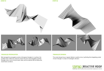
By using a Script that integrates a recursion among other several functions we developed a repetition of triangles capable to adapt to many kind of surfaces by creating subdivisions based on a first geometry.


We managed to propagate a series of irregular triangles in a surface but then we managed to show how a regular division could be done, by finding the integrating points of each triangle in a base of rectangle’s division.


By controlling a random normal extrusion line we obtained the extrusion of the rectangulardivision with very different heights.

By duplicating the function used in the rectangles extrusion, the triangles followed a normal line individual for each one of them with random heights; but going one step behind, instead of extruding the triangle's division, we created a scaled offset of the main triangles and then lofted the two geometries, creating the effect that we were looking for from the beginning.

The roof at the end did accomplish the effect we expected with the lights and shadows, and adapted to the roof of the Institute, with no limits to develop itin any given surface. You can control some parameters within the script, such as the limit of the random height of each pyramid and limit the smallest size you for the base triangles.

IAAC 2007-2008 Scripting
Supervisors: Carlos Barrera, Luis Fraguada
Author: Mariana Paz Castellanos,
Rodrigo Langarica

Thursday, December 4, 2008

PARAMETRIC PIPE

We explored the possibilities that emerge from parametric and associativity integrating tools that are linked to a different design mentality where changes can be made at any moment and perceived in real time propagating the changes through all other associated files.
The main idea was to use the color code R G B for the lighter and the darkest color eye of each one of us, in this way I would have a unique combination for everyone and at the same time I could generate a matrix with 6 independent sets of data for everyone. Along with this, we used some other measurements as the lip’s size creating a matrix which gave us a particular set of data for each one.
After much consideration, we chose to explore other ideas for our parametric design project. We have studied some interesting objects related to lip and eye measurements and decided to develop “pipes” for our final customised element.The final model was simplified after many versions to a simple tube with some circles defining the profile of the element and a central spline structuring the spine of the element. Along with the customized versions for each one of us the most challenging aspect of the model was to establish the correct relationships between the spline and the perpendicular curvature of the circles.

Along with the final model constructed as a tube, a second layer was developed to generate the mesh defining the envelope of the pipes that will serve as a box. Individual components were designed as a base module.

Here is a video showing how the model works in Top Solid:


3d printing: A rapid prototyping model in powder with bonding agent was used to create three models. Once of these models features a texturized surface based on the component mesh generated through parametric design. Electronic files were transferred from Topsolid to Rhino and then saved as a stereography for 3D printing.

Laser cutting: A study model was developed to explore the design of a texturized box that would host the pipe. Files were extracted from Topsolid and unfolded as a flat surface.

IAAC 2007-2008 Parametric Design I
Supervisors: Marta M. Alemany
Authors: Maite Bravo,
Mariana Paz Castellanos, Jordi Roses
http://www.iaacblog.com/parametricdesign1/

PARAMETRIC HOUSE

The basis of the studio was to investigate the impact of digital technologies in architecture, focused in the implementation of parametric design tools and digital fabrication equipment. We took as a basis the "Casa Tolo" by Portuguese architect Alvaro Leite Siza, because we were very interested in a house that coul adapt itself to any given topography as a basis.

Our idea was to develop an associative model capable of adapting itself to the changes of the site, by doing this we created prototype which can be used as many times as needed either for a housing development as mass customization, or in a single house project. By taking control of its main components which will adapt parametrically once the volume is inserted in the topography, the project changes every time the site does. Once the presets are ready, the changes on the house can be made as well, since we can control dimensions, intersections, shapes and program.

- The project had different control parameters, the first set was in a global scale, directly related to site and volumes and the possibility to modify the topography and control the height of each element to remain connected in spite the changes on the site.
- The option to control the position of each block with a certain restraints (always connected to each other) within the site. So you could go uphill, downhill or to either side.
- You could change numerically the width of every element of the house, walls, slabs and ground slab.
- The opening for windows on either side of the element, working with the intersection between each box. The intersection between each box can also be changed numerically, by height or by the width of the staircase.
- The automatic creation of the stairs needed to connect each element respecting the inclination and size of real regulations, this automatically gave the dimensions needed for each element to work with this staircase whether it goes up or down.(boxes length)
Here you can see a video of how the actual model works in Missler's Top Solid:


We created a series of models which represented some of the basic ways the project could work. At the same time, we incorporated a program for each of this chosen configurations, and we ended up making a second set of parameters for one of this possibilites.
The second set of parameters worked in a different scale. The idea was to go further into the possibilites of parametric software in the detailing and actual construction of the house.
- First we projected the topography lines directly to the outer surface of each box, in order to use them as a base for marking the surface, thinking of them as precast concrete elements. - These precast elements can be further developed in another software such as Rhino, in order to subdivide the surface and create a CAM file which could be used for molds of each element. Giving us the chance to subdivide the elements using the same carvings so you would not see the joints.
- On the other hand we were able to control the subdivisions for the profiles of the windows, the size of this profiles, and the number of elements in which to divide the facade.
We went a little further also with the staircase, and you could control the size of each step, the width of the staircase, the with of each step, depending on material needs, and even the railings height, and with according also to the material wished to apply.

Here you can see a video of how this parameters work in Missler's Top Solid:

We created some models in the 3d rapid prototyping printer to show in scal how both the mold and the actual corner piece would work. And we developed the Rhinocam files of the mold considering the use of a 3 axis CNC-Milling Machine with foam.


IAAC 2007-2008 Research Studio in Digital Tectonics
Supervisors: Marta Male, Jose Pedro Sousa
Author: Mariana Paz Castellanos,
Rodrigo Langarica
http://www.iaacblog.com/digitaltectonics/

Tuesday, December 2, 2008

INTERNET 0

The idea of the seminar is to look at the relationship between the web and everyday elements, opening the idea of embedded programed technologies into everyday articles, and specifically to architecture, the next step would be to integrate this to the web, to have a complete network of things working all together from a remote location, or from direct interaction, and this could eventually become linked through the web. There is an interesting article in this matter written by Neil Gershenfeld, Raffi Krikorian and Danny Cohenof the bits and atoms department in MIT.

We all developed a single device which could have touch, sound,light or movement inputs resulting in the same outputs, created a circuit for this, and then we programmed a script to control the circuit, each of us had the possibility of creating an installation where several devices with our own script could interact, or we could explore interaction between devices with different scripts running at the same time.

IAAC 2007-2008 Internet 0
Supervisors: Victor Viña
Author: Mariana Paz Castellanos

3D PRINTING

The challenge was create a pattern that could be wrapping the surface but that remained connected in every way, provoking a complex surface and not only a simple cube with a pattern drawn on its surface. After accomplish that I decided to actually create an inner cube that it could increase the complexity but at the same that related the space with the surface. Then the connector it was the element that it would hold everything together but at the same time would not interfere with the free inner space.

IAAC 2007-2008 Digital Fabrication
Supervisors: Marta Male-Alemany
Author: Mariana Paz Castellanos

CNC MILLING

We tried to create a surface that could give you the sensation of movement throughout a very simple pattern that would work in a three-dimensional way. By simplifying the work and using only one tool we managed to create a surface that has these characteristics but also can give you the sensation of a very complex geometry. We draw a curved pattern and then it was projected to the surface. The parallel finishing it was done only for having a smooth surface on the bottom after the engraving.
IAAC 2007-2008 Digital Fabrication
Supervisors: Marta Male-Alemany
Authors:
Rodrigo Langarica, Mariana Paz Castellanos